In this tutorial we will draw the time line markers on the face of our sundial. These lines are called hour lines even if we divide the hours into smaller units of half or quarter hours. We know a couple of things before we start: the hour lines radiate outward from the base of the gnomon (we'll discuss making the gnomon in the next tutorial). The 6am-6pm hour lines are perpendicular to the 12-noon line, which is aligned north-south.
If we imagine the sun's travel across the sky, we can describe its motion as the number of hours before or after the local noon meridian (the north-south line in the sky that goes directly overhead). The sun's position is known as the hour angle (HA). We need HA in our equations as degrees, not hours. Accepting that there are 360/24 = 15 degrees in an hour of time our equations for hour angle becomes:
Before noon HA = 15*(hour-12) e.g. hour = 10am gives HA = -30
After noon HA = 15*hour e.g. hour = 3pm gives HA = +45
The equation to translate hour angle (HA) into the sundial hour line angle (theta)is
tan(theta) = tan(HA)*sin(lat) where lat = dial's latitude
or theta = arctan(tan(HA)*sin(lat))
To insure that we have no ambiguities in determining theta, we can use the computer function arctan2 to determine the arc tangent using the sine and cosine ratio:
theta = arctan2(sin(HA)*sin(lat),cos(HA))
To implement this in OpenSCAD, we make a long, slender "cube" (its technical name is really rectangular cuboid, but "cube" sufficies even if the sides are unequal) that is oriented toward north (y-axis) and centered on the origin (0,0). Lwidth, Llength, and Lhght will be the width, length and height of the hour line. Once this cube is created, because it is centered on (0,0), we move it one half its length north and raising it one half its height. That sets the base of our slender cube at the origin. Finally we rotate it by the hour line angle theta. All of this is put into a loop using a for statement to step from the first to the last hour line in 15 degree increments:
first = 15*(minHA - 12);
last = 15*(maxHA);
// loop through the hour angles
for(HA=[first:15:last]){
//compute the hour line angle
theta = atan2(sin(lat)*sin(HA),cos(HA));
//instantiate the hour line at angle theta using a slender cube
rotate([0,0,theta])
//translate the hour line to have its base at (0,0)
translate([0,Llength/2,Lhght/2])
cube([Lwidth,Llength,Lhght],center=true);
}
Technically the hour lines are in the right position, but they are a bit "raw". So we need to trim them. The easiest way is to create a donut mask and then intersect the mask with the hour lines. Here is a simple module to construct the donut mask using a ring size of Din, Dout, and Dhght representing the ring's inner and outer diameter and height;
module donut_mask(Din, Dout, Dhght){
difference(){
cylinder(d=Dout,h=Dhght);
cylinder(d=Din,h=3*Dhght,center=true);
}
}
Note that the donut mask uses a "cut-out" inner cylinder that is taller than the outer cylinder. This is to insure that no face pieces remain in the center. The intersection of the hour lines and the donut mask is straightforward. As with procedures above, we use parametric variables such as dial_top (the diameter of the dial), and the hour line dimension Lwidth, Llength, and Lhght. The result is:
theta = atan2(sin(lat)*sin(HA),cos(HA));
intersection(){
donut_mask(Din, Dout, Lhght);
rotate([0,0,theta])
translate([0,Llength/2,Lhght/2])
cube([Lwidth,Llength,Lhght],center=true);
}
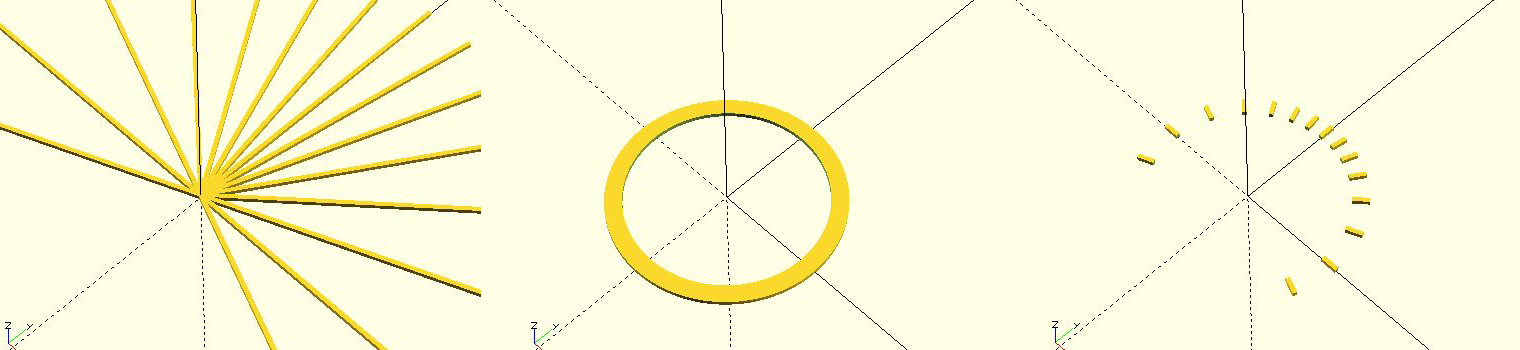
Figure 1. (a) raw hour lines, (b) donut mask, (c) intersection of hour lines and mask
Are we done? We've designed a dial with the gnomon foot in the middle of the dial. This to me is artistically unbalanced as the southern part of the dial is totally vacant. So let's offset the gnomon and the center of the hour lines by a distance called Loffset to the south of the dial, expanding the useable area of the dial. For example I prefer Loffset to be about a quarter of the dial's diameter. The above code needs only one additional line:
theta = atan2(sin(lat)*sin(HA),cos(HA));
intersection(){
donut_mask(Din, Dout, Lhght);
translate([0,-Loffset,0])
rotate([0,0,theta])
translate([0,Llength/2,Lhght/2])
cube([Lwidth,Llength,Lhght],center=true);
}
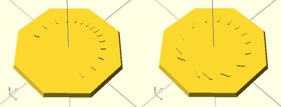
Figure 2. (a) centered hour lines & gnomon foot, (b) offset hour lines & gnomon foot
Download the OpenSCAD code from the attachment below that includes both Part 1 and Part 2 tutorials.
| [ ] | 4 kB |