
- Details
- Hits: 14817
![]() Look for the new menu tab:3D Printing Tips. Starting this December (2019) NASS begins a series of tutorials using OpenSCAD and other software for designing and printing 3D objects. As you might guess, we'll focus on creating sundials and other shadow casting objects. Download your copy of OpenSCAD at http://www.openscad.org and join our tutorials. If you want even more detail on 3D sundials, join NASS and receive The Compendium with Bill Gottesman, Steve Lelievre, Bob Kellogg and others writing in the regular column "3D Design and Printing Sundials."
Look for the new menu tab:3D Printing Tips. Starting this December (2019) NASS begins a series of tutorials using OpenSCAD and other software for designing and printing 3D objects. As you might guess, we'll focus on creating sundials and other shadow casting objects. Download your copy of OpenSCAD at http://www.openscad.org and join our tutorials. If you want even more detail on 3D sundials, join NASS and receive The Compendium with Bill Gottesman, Steve Lelievre, Bob Kellogg and others writing in the regular column "3D Design and Printing Sundials."
- Details
- Hits: 12850
The goal of our first program is to create the dial base. We'll define the dial base parametrically using three parameters for size: dial_btm, dial_top and dial_hght. This allows for the diameter of the base bottom and top to create tapered sides and base height.
Normally we think of making a cylinder using an OpenSCAD function called cylinder(h, d) where h is the height and d is the diameter. There is an extension of parameters such that the cylinder can be tapered using cylinder(h,d1,d2) where d1 is the base diameter and d2 is the top diameter.
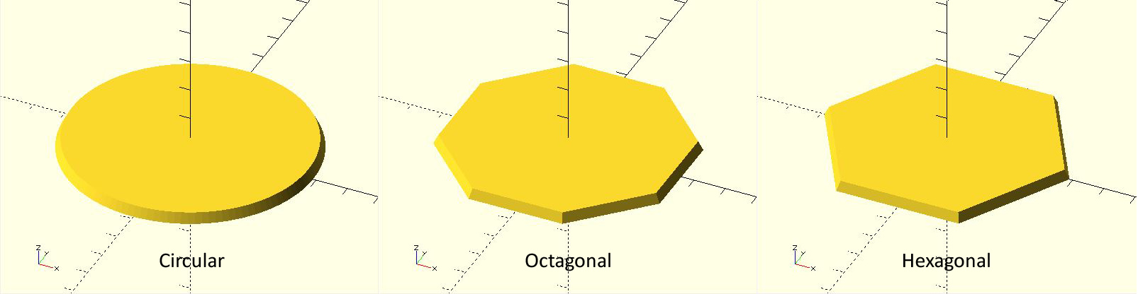
But suppose that we want to make the sundial base in the shape of a hexagon or octagon. We rely on a special OpenSCAD variable $\( \)fa that sets the minimum angle of our solid. Two or three degrees on the edge makes a nice circle, 45 degrees for each side makes an octagon and 60 degrees for each side makes a hexagon. It makes sense that we could invoke the cylinder functionfor a tapered hexagon as:
cylinder( \(fa=45,h,d1,d2);
We'd like to invoke "if" statements to decide which shape to make. The code takes the form of
if(shape=="hexagon") { make our tapered cylinder look like a hexagon }
The "if" statements (as well as "for") statements in OpenSCAD are handled a bit different than normal code. Whatever happens within the "if" or "for" statement stays within it. Variables can't leak out. Therefore we must build the sundial base within each selection of the choices "circular", "hexagon", or "octagon". Thinking of terms of modular procedures, we can invoke a module called "sundial_base" that takes the appropriate parameters to create one of these three base shapes.
In the attached exemplar code, the size variables of the base (dial_btm, dial_top, dial_hght) from the main program are used directly within the "if" statement as well as within the sundial_base module. The hierarchy of variable scope allows these mainl variables to "fall" into these subservient functions and procedures. However, within each "if" statement we need to set local paramaters to properly create the desired shape. So within each "if" statement we create two variables to (1) set minimum segment angle and (2) rotate the base such that the hexagon or octagon has a flat side parallel to the x-axis.
The necessary rotation of the sundial base shows another peculiarity of the OpenSCAD code. In mathematics one writes the translation or rotation operator (a matrix) to the left of the object being changed. OpenSCAD does this by writing the operator on the lines before the object. And there is a subtle use of the ";" symbol to indicate the end of operation:
Download the OpenSCAD code from the attachment below.
| [ ] | 2 kB |
- Details
- Hits: 9679
In this tutorial we will draw the time line markers on the face of our sundial. These lines are called hour lines even if we divide the hours into smaller units of half or quarter hours. We know a couple of things before we start: the hour lines radiate outward from the base of the gnomon (we'll discuss making the gnomon in the next tutorial). The 6am-6pm hour lines are perpendicular to the 12-noon line, which is aligned north-south.
If we imagine the sun's travel across the sky, we can describe its motion as the number of hours before or after the local noon meridian (the north-south line in the sky that goes directly overhead). The sun's position is known as the hour angle (HA). We need HA in our equations as degrees, not hours. Accepting that there are 360/24 = 15 degrees in an hour of time our equations for hour angle becomes:
Before noon HA = 15*(hour-12) e.g. hour = 10am gives HA = -30
After noon HA = 15*hour e.g. hour = 3pm gives HA = +45
The equation to translate hour angle (HA) into the sundial hour line angle (theta)is
tan(theta) = tan(HA)*sin(lat) where lat = dial's latitude
or theta = arctan(tan(HA)*sin(lat))
To insure that we have no ambiguities in determining theta, we can use the computer function arctan2 to determine the arc tangent using the sine and cosine ratio:
theta = arctan2(sin(HA)*sin(lat),cos(HA))
To implement this in OpenSCAD, we make a long, slender "cube" (its technical name is really rectangular cuboid, but "cube" sufficies even if the sides are unequal) that is oriented toward north (y-axis) and centered on the origin (0,0). Lwidth, Llength, and Lhght will be the width, length and height of the hour line. Once this cube is created, because it is centered on (0,0), we move it one half its length north and raising it one half its height. That sets the base of our slender cube at the origin. Finally we rotate it by the hour line angle theta. All of this is put into a loop using a for statement to step from the first to the last hour line in 15 degree increments:
first = 15*(minHA - 12);
last = 15*(maxHA);
// loop through the hour angles
for(HA=[first:15:last]){
//compute the hour line angle
theta = atan2(sin(lat)*sin(HA),cos(HA));
//instantiate the hour line at angle theta using a slender cube
rotate([0,0,theta])
//translate the hour line to have its base at (0,0)
translate([0,Llength/2,Lhght/2])
cube([Lwidth,Llength,Lhght],center=true);
}
Technically the hour lines are in the right position, but they are a bit "raw". So we need to trim them. The easiest way is to create a donut mask and then intersect the mask with the hour lines. Here is a simple module to construct the donut mask using a ring size of Din, Dout, and Dhght representing the ring's inner and outer diameter and height;
module donut_mask(Din, Dout, Dhght){
difference(){
cylinder(d=Dout,h=Dhght);
cylinder(d=Din,h=3*Dhght,center=true);
}
}
Note that the donut mask uses a "cut-out" inner cylinder that is taller than the outer cylinder. This is to insure that no face pieces remain in the center. The intersection of the hour lines and the donut mask is straightforward. As with procedures above, we use parametric variables such as dial_top (the diameter of the dial), and the hour line dimension Lwidth, Llength, and Lhght. The result is:
theta = atan2(sin(lat)*sin(HA),cos(HA));
intersection(){
donut_mask(Din, Dout, Lhght);
rotate([0,0,theta])
translate([0,Llength/2,Lhght/2])
cube([Lwidth,Llength,Lhght],center=true);
}
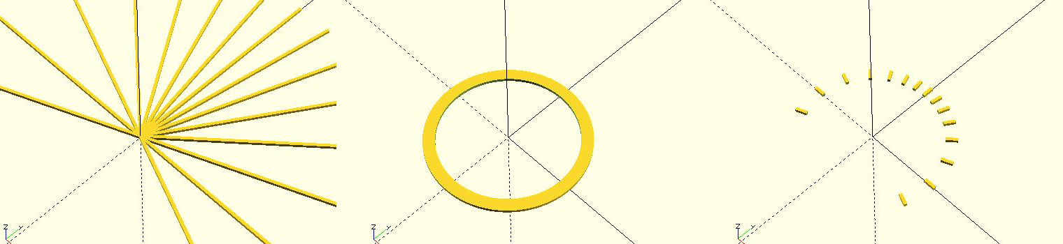
Figure 1. (a) raw hour lines, (b) donut mask, (c) intersection of hour lines and mask
Are we done? We've designed a dial with the gnomon foot in the middle of the dial. This to me is artistically unbalanced as the southern part of the dial is totally vacant. So let's offset the gnomon and the center of the hour lines by a distance called Loffset to the south of the dial, expanding the useable area of the dial. For example I prefer Loffset to be about a quarter of the dial's diameter. The above code needs only one additional line:
theta = atan2(sin(lat)*sin(HA),cos(HA));
intersection(){
donut_mask(Din, Dout, Lhght);
translate([0,-Loffset,0])
rotate([0,0,theta])
translate([0,Llength/2,Lhght/2])
cube([Lwidth,Llength,Lhght],center=true);
}
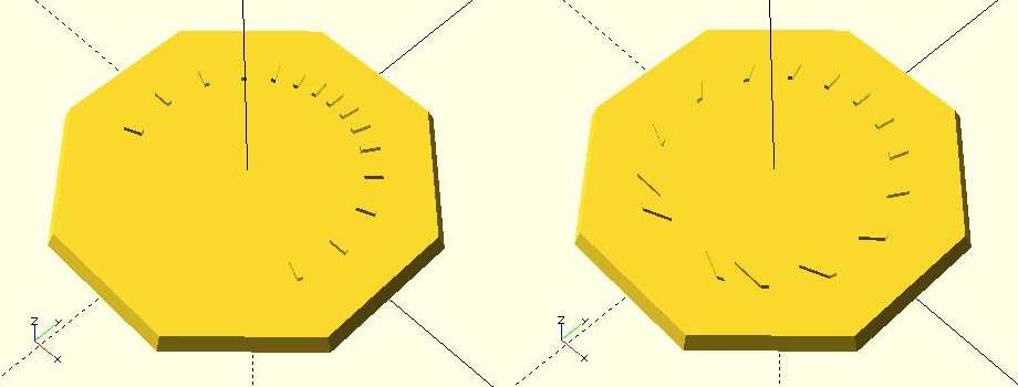
Figure 2. (a) centered hour lines & gnomon foot, (b) offset hour lines & gnomon foot
Download the OpenSCAD code from the attachment below that includes both Part 1 and Part 2 tutorials.
| [ ] | 4 kB |
- Details
- Hits: 10711
 In the March 2020 issue of The Compendium (Vol. 27-1) from NASS I discussed how to make a simple triangle gnomon. We'll extend this tutorial to add a rounded tip and then examine how to make a gnomon with an underneath cut-back for a more pleasing shape.
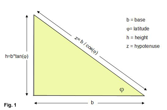
The fundamental triangle has a base b, height h, and hypotenuse z. To make the triangle proportions for the sundial latitude \(\phi\), we observe that the hypotenuse must point to the north (or south) celestial pole. As shown in (Fig. 1) :
We'll start out making the gnomon in a self-contained OpenSCAD module that at first simply creates the gnomon in the x-y plane. Here's the code:
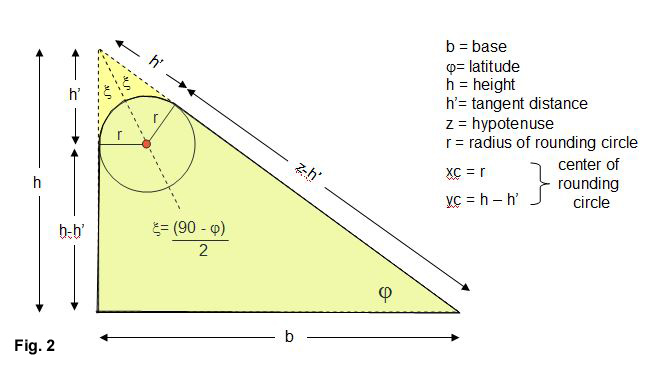
In the full code, we'll rotate and translate the gnomon so that it sits on top of the sundial we've designed inthe previous tutorials. But first, let's improve the gnomon with a rounded tip. From Fig. 2 we see that the rounding circle is centered on a bisected line from the apex and is tangent to both triangle's vertical and hypotenuse sides. We've labeled the tangent distance from the apex as h' on these sides. If we specify the rounding circle's radius r we see that the apex triangle half-angle \(\xi\) can be derived from the sum of angles equal to 180 degrees. Rearranging we get:
\( h' = \frac{r}{tan\xi} \)
The x-y tangent coordinate on the vertical side of the triangle is [0,h-h']. The x-y tangent coordinate on the hypotenuse is a bit more complicated, giving [b - (z-h')* cos\(\phi\), (z-h')*sin\(\phi\)]. These points help create a 4-point polygon to which we add the rounding cylinder:
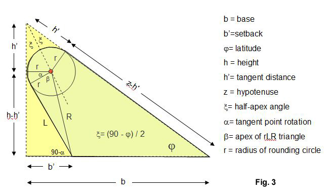 Now let's go even further by using a setback of the base where we move the vertical portion of the triangle back underneath the hypotenuse. The setback rotates the exact point of tangency with the rounding circle, so that we need a little more trignometry. In Fig. 3 the new gnomon setback line is L. To determine L we use the circle center to setback distance R as well as determining the apex angles alpha and beta:
\( R=\sqrt{(b'-r)^2+(h-h')^2}\)
The length R and rounding circle radius give the apex angle \(\beta\):
All that remains is finding \(\alpha\). We see that the side L is actually part of two triangles. One is the rLR triangle with apex angle \(\beta\) and the other triangle is made from the setback b' and angle 90-\(\alpha\). Two equations can be formed which after some algebra reduces to:
 \(\frac{ (b'-r) - r*cos\alpha} {L} = -sin\alpha\)
Adding them together and rearranging
\(cos\alpha = \frac{r*(r-b') + L*(h-h') } {r^2 + L^2 }\)
With \(\alpha\) the indented tangent point is easily found as
Pick up the attached OpenSCAD tutorial file and see the full code to attach either the simple, rounded, or setback gnomon onto you dial. In the next tutorial, we'll add hour numbers to the dial.
| [ ] | 8 kB |
- Details
- Hits: 6507
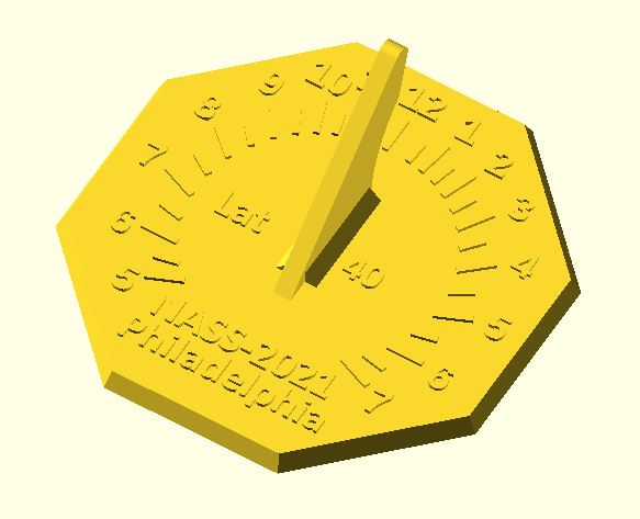
Here in the last in our series on making a sundial using OpenSCAD we need to finish the dial by draw the hour numbers. We know that the hour angle as measured at the foot of the gnomon is:
tan(theta) = sin(lat)*sin(HA)
where HA is the hour angle from noon (15 deg for each hour)
lat is the latitude
theta is the hour line
theta = atan2(sin(lat)*sin(HA), cos(HA))
ao = 1
bo = -2*goffset*cos(theta)
co = goffset^2 - crad^2
The idea is to set up a loop for drawing the hour numbers. Let's say that we want to put down the numbers 5(am) to 7(pm). On a 24 hour scale, that's H = 5:19. Meanwhile that hour angle referenced to the 12-noon hour is HA = 15*(H-12) degrees.
 module draw_hour_number(HA,H,gnomon_width) {
//text of one hour number
if (H>12) {
txt3 = str(H-12);
}else{
txt3 = str(H)
}
//classic hour line
theta = atan2(sin(latitude)*sin(HA),cos(HA));
if H {
wo = gnomon_width;
}else{
wo = -gnomon_width;
}
//this is a distance goffset from the dial center. We need to use the quadratic
//equation to get the distance from the gnomon foot to a circular arc (chapter ring)
//of radius crad where our numbers will be placed...
push = 1.15; //tweak to move the number a bit further out on the dial face
ao = 1;
bo = -2*goffset*cos(theta);
co = goffset*goffset - crad*crad;
zo = push*abs((-bo - sqrt(bo*bo-4*co))/(2*ao));
//translate this to the dial x,y coordinate system
xo = zo*sin(theta) + wo/2; //remember that wo may be positive or negative
yo = zo*cos(theta) + goffset; //goffset is a negative number since moved gnomon south of center
//print the number
translate([xo,yo,dial_thickness]) //raise the number to sit at the top of the dial face thickness
linear_extrude(height = ho) //ho is the thickness (height) of our number
text(txt3, size = 4.5, halign = "center",font = str("Angsana:style=Bold"), $fn = 16);
}
The final OpenSCAD code to create this simple horizontal sundial is attached. Download it and have fun.
| [ ] | 11 kB |